Retrofitting an LED fixture can seem simple until the old shell reveals warped metal, brittle insulation, or limited internal space. This guide explains How to install a driverless LED PCB into an existing shell? It focuses on practical decisions, not shortcuts. A driverless PCB may connect directly to mains voltage, so compatibility, insulation, grounding, and enclosure condition require careful attention. Always disconnect power before opening the fixture. Confirm local electrical requirements and follow the PCB manufacturer’s instructions.
Begin by inspecting the shell, mounting points, wire routes, and available clearance. Measure the cavity with a ruler, then compare those dimensions with the PCB, terminals, and protective barriers. The board should sit firmly without touching conductive metal. Use approved spacers, heat-resistant supports, and suitable wiring. Do not rely on adhesive alone. Check polarity, input voltage, power rating, and dimming compatibility before making connections. A small mismatch can damage the board or create excessive heat. It happens more often than expected.
Thermal management is equally important. Clean dust from the shell and ensure the PCB can transfer heat through its designed mounting surface. After installation, inspect every connection for looseness, exposed conductors, and sharp edges. Test insulation and continuity with appropriate equipment before restoring power. Then run the fixture briefly and monitor unusual flickering, odor, noise, or rising temperature. Stop immediately if anything seems abnormal. Even experienced technicians can miss a cramped wire or an imperfect contact. A careful review improves reliability and protects the finished fixture. Where uncertainty remains, consult a qualified electrician or the PCB manufacturer rather than guessing.
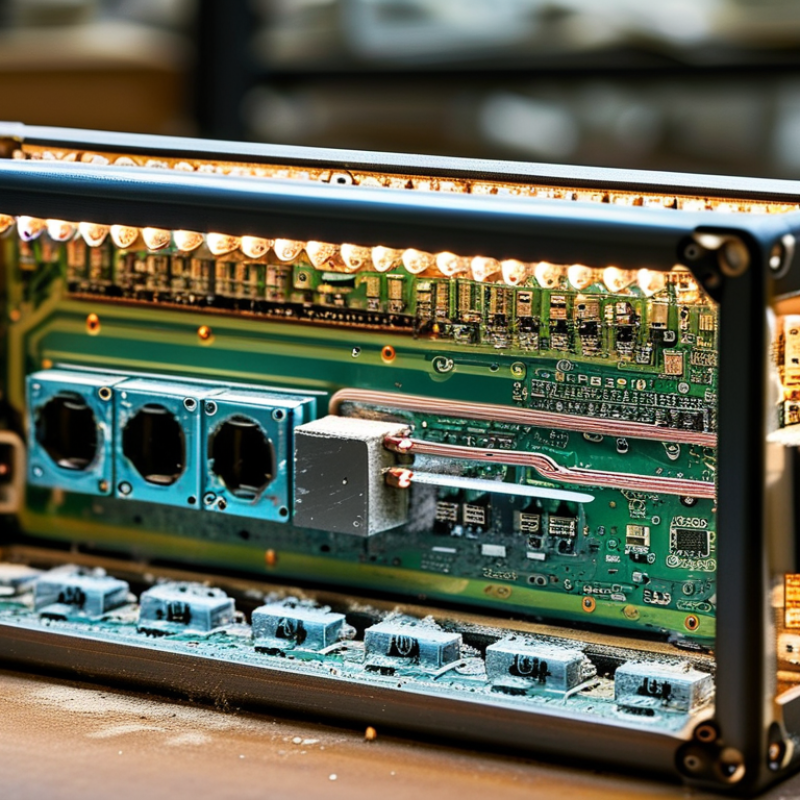
Before choosing a driverless LED PCB, inspect the existing shell as a complete electrical and thermal system. Remove power and record the old board’s diameter, mounting holes, wire position, and lens clearance. A caliper helps. Check the input voltage, current, and polarity printed inside the housing. Do not trust appearance alone; two similar boards may require different electrical conditions. Look for corrosion, brittle insulation, loose screws, and darkened plastic near the light source. These signs can indicate excessive heat or previous electrical stress.
Compatibility also depends on heat transfer. Measure the shell’s metal contact area and clean it before installation. The PCB should sit flat, with suitable thermal compound or an approved interface pad. Avoid stacking washers or bending the board to force alignment. That is risky. Confirm the shell can keep the LED junction temperature within the PCB supplier’s stated limit, using its test method when available. If no thermal data exists, treat the conversion as uncertain and choose a lower-power board. I have seen bright prototypes fail early because the housing felt cool while the board ran hot.
Select the PCB by matching voltage range, power, color temperature, lumen output, dimensions, and mounting pattern. Verify dimming behavior and startup performance if the original lamp used controls. Driverless designs may require a compatible external supply or specified mains connection; never guess from the connector shape. Review insulation, spacing, grounding, and enclosure requirements against local electrical standards. A qualified technician should test isolation, polarity, current, and temperature before closing the shell. The lens may trap heat or shift the beam, so test the assembled lamp, not only the bare PCB.
How to Install a Driverless LED PCB in an Existing Shell?
Preparing Tools, Workspace, and Electrical Safety Measures
Prepare a clean, dry workspace before opening the existing lamp shell. Use a nonconductive mat, bright lighting, and a small tray for screws. Gather insulated screwdrivers, wire cutters, a voltage tester, a multimeter, heat-resistant wire, and eye protection. A camera helps record the original wire positions. I also keep a written sketch, because memory becomes unreliable during reassembly.
Disconnect the power completely, then verify the circuit with a properly rated tester. Do not trust the wall switch alone. Driverless LED PCBs may connect directly to mains voltage, so treat every conductor as energized until testing proves otherwise. Allow capacitors time to discharge, and check again before touching the board. Keep one hand away from the assembly when practical. Never work with wet hands or damaged insulation.
Inspect the shell for sharp edges, loose terminals, dust, and heat damage. Remove debris without scraping nearby wiring. Confirm that the replacement PCB fits without pressure or contact with metal parts. Check polarity, input markings, mounting holes, and required airflow before making connections. The shell should not pinch wires when closed. I once overlooked a slightly raised screw head; it touched the board and created a dangerous weak point. That mistake changed my inspection routine. If test readings seem uncertain, stop and ask a qualified electrician to assess the installation.
Verify the existing shell's nominal AC supply before selecting or connecting a driverless LED PCB. The chart shows common nominal RMS voltage categories found in electrical systems; actual measurements may vary within permitted tolerances.
Before installing a driverless LED PCB, disconnect the fixture from power and verify it with a suitable tester. Existing shells may contain brittle clips, heat-darkened wires, or hidden screws. Photograph the wiring and component positions before removing anything. This record can prevent confusion later. Wear cut-resistant gloves, then use a non-marring pry tool around the edge. Do not rush.
Remove screws with the correct bit to avoid damaging the heads. Support the shell with one hand while loosening each fastener. For soldered wires, desolder them carefully instead of pulling on the pads. Label each wire with temporary markers. Keep it flat. If adhesive holds the old board, warm the area gradually and test a hidden section first. Excessive heat can soften plastic or distort a reflector. I once used too much force on a stubborn clip; the shell survived, but the clip never fitted tightly again. Less force is safer.
After removal, inspect the shell for cracks, melted areas, sharp edges, and damaged insulation. Clean dust with a dry, lint-free cloth rather than aggressive solvents. Check that the new PCB sits evenly without pressure points. Any loose metal fragment should be removed before wiring. If the fixture connects directly to mains power, a qualified technician should verify the connections and insulation. Small mistakes are easy to overlook. Take a final pause before installation.
How to Install a Driverless LED PCB in an Existing Shell?
Mounting and Connecting the Driverless LED PCB Step by Step
Begin with a complete power shutdown. Remove the old board and photograph every wire before disconnecting it. Check the shell for cracks, corrosion, loose screws, and sharp edges. The new PCB must sit flat against a clean thermal surface. Apply a thin, even layer of thermal compound, then secure the board with suitable screws and insulating washers. Do not overtighten them. A distorted PCB can develop hidden stress.
Driverless designs connect directly to mains voltage, so terminal spacing and insulation deserve careful attention. Follow the PCB wiring diagram, not the old lamp’s color assumptions. Keep live wires away from the aluminum body. Add strain relief where the cable enters the shell. The U.S. Department of Energy reports that LED lighting can use at least 75% less energy and last up to 25 times longer than incandescent lighting. These benefits depend on correct installation and heat control.
Before closing the shell, inspect solder joints and gently pull each connection. I still recheck polarity twice. A small mistake matters. Energize the unit through a protected test supply, then measure surface temperature after 30 minutes. The board should illuminate evenly, without flicker, odor, or abnormal noise. The International Energy Agency identifies efficient lighting as an important electricity-saving opportunity, but efficiency is not a substitute for electrical safety. I once ignored a slightly loose mounting screw; the board later showed uneven brightness. Rework is slower than checking.
| Step | Installation Stage | Action | Typical Data or Requirement | Tools and Materials | Acceptance Check | Status |
|---|---|---|---|---|---|---|
| 1 | Confirm electrical compatibility | Read the PCB marking and verify that the input voltage, frequency, LED load, polarity, and approved enclosure type match the existing shell. | Common mains ratings are 120 V AC, 60 Hz or 220–240 V AC, 50/60 Hz. Use only the exact rating printed on the PCB. | PCB datasheet, product label, multimeter, protective gloves | The supply voltage and frequency agree with the PCB rating, and the LED load is within the stated operating range. | Required |
| 2 | Disconnect and inspect the shell | Switch off the circuit breaker, isolate the circuit, and verify that no voltage remains before opening the existing fixture. | Confirm 0 V AC between the line, neutral, and protective-earth conductors before handling the PCB. | Two-pole voltage tester or CAT-rated multimeter, insulated screwdriver, lockout tag | No voltage is detected, the old wiring is undamaged, and the shell has no sharp edges, corrosion, loose parts, or heat damage. | Safety Critical |
| 3 | Remove the previous light source | Remove the lamp, ballast, driver, reflector, or mounting plate that is not part of the new driverless PCB assembly. | A driverless PCB normally connects directly to the specified AC input. Do not leave an old electronic driver or ballast in series unless the PCB instructions specifically require it. | Screwdriver set, nut driver, pliers, container for fasteners | The electrical path is clear, unused components are removed, and the shell remains mechanically stable. | Inspect |
| 4 | Measure the available mounting area | Measure the shell interior and compare it with the PCB outline, hole pattern, connector position, and cable-entry location. | Maintain at least 2–3 mm clearance from metal edges when permitted by the PCB instructions. Do not cover ventilation openings or touch conductive parts. | Steel ruler or caliper, pencil, template, mounting-hole gauge | The PCB fits without bending, forced contact, obstruction of terminals, or interference with the diffuser. | Required |
| 5 | Prepare electrical insulation | Install an insulating pad, approved spacers, or an insulated mounting plate where the PCB could contact the metal shell. | Use non-conductive mounting hardware or manufacturer-specified insulated washers. Keep the PCB underside separated from grounded metal unless the construction explicitly allows direct contact. | Insulating pad, nylon spacers, insulated washers, approved screws | No exposed solder joint or conductive track can contact the shell during normal operation or vibration. | Safety Critical |
| 6 | Install the PCB mechanically | Align the PCB with the existing shell and fasten it evenly through the designated mounting points. | Use all available mounting points where specified. Tighten fasteners firmly without cracking the PCB or distorting the board. Do not drill through copper traces or components. | Screwdriver, torque driver if specified, insulated spacers, washers | The PCB is secure, level, free from movement, and clear of the diffuser, reflector, and shell edges. | Inspect |
| 7 | Prepare the input conductors | Cut the conductors to a practical length, strip only the required insulation, and route them away from hot surfaces and sharp edges. | Use conductor size and insulation temperature rating required by the PCB and local electrical code. A common small-fixture range is 0.5–0.75 mm² copper conductor, but the specified rating takes priority. | Wire stripper, side cutters, cable grommet, strain-relief clamp | Insulation is not nicked, no bare conductor is exposed outside the terminal, and the cable entry has proper strain relief. | Required |
| 8 | Connect line and neutral | Connect the incoming line conductor to the PCB terminal marked L and the neutral conductor to the terminal marked N. | For direct AC input, typical identification is brown or black = line and blue or white = neutral, subject to local wiring standards. Follow the PCB markings, not color alone. | Insulated screwdriver, ferrules if required, terminal torque specification, circuit tester | Each conductor is fully inserted, firmly clamped, correctly identified, and electrically isolated from adjacent terminals. | Safety Critical |
| 9 | Connect protective earth | If the shell is Class I and has an earth terminal, bond the protective-earth conductor to the shell using the designated grounding point. | Typical protective-earth identification is green/yellow. The earth connection must remain mechanically secure and must not be routed through the PCB unless the PCB has a dedicated earth terminal. | Earth conductor, ring terminal, grounding screw, continuity tester | Protective-earth continuity is confirmed between the supply earth and the metal shell; the earth path is independent of the LED PCB. | Safety Critical |
| 10 | Secure and dress the wiring | Fasten the wires so they cannot contact LED components, hot areas, sharp edges, or moving parts. | Keep wiring clear of the LED emitting surface and provide slack near the terminal without placing tension on the PCB. Use flame-retardant, temperature-rated ties or clips where required. | Cable clips, approved cable ties, edge grommet, heat-resistant sleeve | No wire can be pulled from the terminal, pinched by the diffuser, or damaged when the shell is closed. | Inspect |
| 11 | Complete pre-power checks | Inspect terminal polarity and mechanical clearances, then test for unintended continuity between line, neutral, and the shell. | Confirm correct terminal identification, secure fasteners, intact insulation, and no short circuit. Use the applicable insulation-resistance and protective-earth tests required by local code. | CAT-rated multimeter, insulation tester where required, continuity tester | All test results meet the applicable electrical standard and the PCB wiring diagram. | Required |
| 12 | Reassemble the shell | Replace the diffuser, reflector, gasket, cover, and all retaining hardware without pressing against the PCB or wiring. | Preserve the original ingress protection, ventilation path, and optical spacing. Replace damaged gaskets and close every unused cable opening. | Diffuser, gasket, screws, appropriate screwdriver, inspection light | The shell closes evenly, all covers are secure, and no wire is trapped or visible through an unintended opening. | Inspect |
| 13 | Perform controlled power-up | Restore power while standing clear of the fixture and observe the initial start-up behavior. | Check for stable illumination, no flicker, abnormal noise, burning odor, smoke, excessive heat, or tripped protection. Disconnect power immediately if any abnormal condition occurs. | Protective equipment, clamp meter if required, light meter if available | The PCB starts normally, illumination is uniform, and the measured input current is within the PCB specification. | Safety Critical |
| 14 | Verify thermal performance | Operate the fixture long enough to reach a stable temperature, then inspect the PCB, shell, and surrounding materials. | Use the maximum case or ambient temperature stated for the PCB. Do not exceed the rated temperature, and do not obstruct heat-dissipation surfaces. | Contact thermometer or infrared thermometer, inspection checklist | Temperature remains within the PCB specification, the shell is stable, and there is no discoloration, odor, or heat-related deformation. | Verify |
When I retrofit a driverless LED PCB into an existing shell, I treat light testing as part of installation. I remove dust, old wiring, and loose reflectors before positioning the PCB. The shell must provide enough clearance for heat to escape. I also inspect every terminal for damage or exposed conductor. Power stays disconnected during this work. A qualified electrician should verify mains connections and local safety requirements. That check matters.
After mounting the PCB, I energize it briefly and watch for flicker, delayed starting, or uneven brightness. I use a lux meter at several points across the diffuser. Dark corners often reveal poor alignment or insufficient spacing. I also check the PCB temperature after thirty minutes under normal conditions. A warm surface may be acceptable, but rapid temperature rise needs attention. I once judged a fitting by brightness alone. That was a mistake. It looked fine at first, yet the center became noticeably hotter than the edges.
For the final installation, I secure the PCB with suitable insulated supports or heat-resistant fasteners. I avoid placing pressure directly on the circuit board. Wires need gentle bends, firm strain relief, and clear separation from sharp metal edges. The diffuser should sit evenly without touching hot components. I lightly test the assembly for movement after tightening the screws. If anything shifts, I correct it before closing the shell. I photograph the wiring and record the test results for future servicing. Small gaps can still appear after reassembly, so I inspect the seal again the next day.
: Prepare insulated screwdrivers, wire cutters, a voltage tester, and a multimeter. Use eye protection and a nonconductive mat. Keep screws in a small tray. A camera can record original wire positions.
Choose a clean, dry area with bright lighting. Disconnect power completely before opening the shell. Do not trust the wall switch alone. Keep wet hands away. Keep it dry.
It may connect directly to mains voltage. Treat every conductor as energized until testing proves otherwise. Allow capacitors time to discharge. Test again before touching the board. If readings seem uncertain, stop.
Photograph the wiring before disconnecting anything. Remove screws with the correct driver bit. Support the shell while loosening fasteners. Desolder wires carefully instead of pulling the pads. Use a non-marring pry tool around clips.
Check for cracks, melted plastic, sharp edges, dust, and damaged insulation. Remove loose metal fragments with care. Clean surfaces using a dry, lint-free cloth. Avoid aggressive solvents. Small damage matters.
Confirm the PCB fits without touching metal parts. Place it flat against a clean thermal surface. Apply a thin, even layer of thermal compound. Use suitable screws and insulating washers. Do not overtighten them.
Follow the PCB wiring diagram, not assumed wire colors. Check polarity and input markings carefully. Keep live wires away from the aluminum body. Add strain relief where the cable enters the shell. Never pinch wires when closing the shell.
Inspect solder joints and gently pull each connection. Recheck polarity twice. Use a protected test supply when possible. After 30 minutes, measure the surface temperature. Stop if you notice flicker, odor, noise, or uneven brightness. I once missed a loose screw. Rechecking is worth the time.
This guide explains How to install a driverless LED PCB into an existing shell? It begins by checking the shell’s dimensions, mounting points, ventilation, and electrical compatibility before selecting a suitable driverless LED PCB. Careful preparation is essential, including gathering insulated tools, cleaning the workspace, disconnecting power, and confirming that all electrical connections are safe to handle. The existing lighting parts should then be removed gently to preserve the shell and avoid damaging wiring, clips, or reflective surfaces.
Next, the LED PCB is positioned securely and connected according to its electrical requirements, with attention to polarity, insulation, and heat dissipation. Once installed, the system should be tested for stable illumination, even light distribution, excessive heat, flickering, or unusual odors. Any issue should be corrected before final assembly. After confirming reliable performance, the PCB and wiring can be secured neatly inside the shell, leaving the finished lighting unit safe, clean, and ready for regular use.

Jamaica Light